
Antenna kits created and sold by K4QCD
The Everything


This is four full antennas in one. I believe it is easier to complete the antenna in the order of the instructions. However, you can do either side first.
ATTENTION - This antenna is meant to be use one transformer at a time with one radio at a time. Only one antenna wire should be connected at a time. Make sure you are connected to the correct BNC for the transformer you plan to use.
General Instructions
-You have 8 lengths of magnet wire so you can alternate colors to distinguish between wires. 5 wires will be used on one side and 3 on the other. It's best to separate the wire you are using for each side before hand to make sure you don;t end op having too many of one color and too few of the other on a particular side. You could have 5 red wires and 3 copper color or the other way around...so long as you can alternate the colors. Also, the copper colored wires are enameled. You need to strip the enameling off of those also for a good connection.
-The 1:1 dipole option uses its own BNC connection. The 49:1, 9:1, and 4:1 all share a common BNC connection. This works fin as long as you only connect only one radiating element at a time. NOTE that this does add some capacitance to the system, so you'll end up using shorter than typical wire for your radiating element. as with any wire antenna check SWR and trim appropriately for the frequencies you plan to operate on.
-The counterpoise connection is connected to the ground of both BNCs. It's not replay needed for a 1:1, but it can be used for any of the 49:1, 9:1 and 4:1
Side 1
1) Make sure you are looking at the side of the board as picture below. All solder points are through hole and labeled from the top side. Don't let the through holes from the other side confuse you.

2) Take one of the provided toroids and one length of the magnet wire. Fold about 6 inches of the wire back on itself, and wind that section together for the 49:1 winding. Do the first two wraps of the twisted wire, then take two more lengths of wire (alternating color) and start wrapping. Wrap as shown bellow. This is wrapping for a 49:1 and a 1:1 on the same toroid. Green numbers are the number of wrappings for the 1:1 and the black are the number of wrappings for the 49:1. Take care to not cross the wires as your wrap.

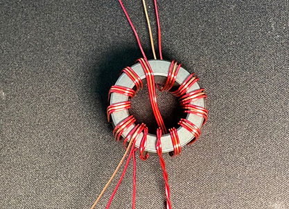
3) Bend the wire to align with the through holes. The twisted pair goes through the big hole labeled shield on the far right and the single bottom wire for the 49:1 wrapping goes through the hole labeled center in the middle. The 1:1 wrapping will go into the holes labeled center and shield on the left. At the top The wire corresponding the the 49:1 will go into he hole labeled ant and the 1:1 wrapping will go into the holes labeled center and shield at the top. IMPORTANT - It is best to check continuity to make sure you using the corresponding wires. You'll need to scrap the enamel off to get a good connection when checking continuity.


4) With the wires inserted in the through holes snip the wire to just fit through the holes. Strip the enamel off the wire where it goes through the holes so there will be good contact, then solder them into place. (don't judge my solder job. I don't claim to be good at it.)

Side 2
1) Make sure you are looking at the side of the board as picture below. All solder points are through hole and labeled from the top side. Don't let the through holes from the other side confuse you.

2) Take one of the provided toroids and five lengths of the magnet wire (alternating colors). Wind the toroid with the magnet wire as shown. Be sure not to cross the wires as you wind. Using the alternating colors will let you distinguish between the wires. This will be the windings for a 9:1 and a 4:1 on the same toroid. Wires 1, 2, & 3 will wrap through the center of the toroid 9 times. Wire 4 & 5 will wrap through the center of the toroid 8 times.


3) Bend and align the wires to the holes. It is best to check continuity to make sure you are making the connections correct. You will need to use a razor blade or something else to strip some enamel off to check continuity. Insert the wires and trim them so they are just through the board. Strip the enamel off the wire so it will make good contact, and solder them into place. the holes are labeled 1 through 5 on each side. The wire going into hole 1 on the left should be the same wire going into hole 1 on the right and so on.


Bolts and Heat Shrink
1) Take the provided lock nuts and bolts and bolt them onto the board. Put the wing nuts on last so they don't get in the way when putting the heat shrink on. Technically it doesn't matter which way you put them on, but I do it where the wing nut is up towards the side of the board it goes to as you see in the photos. This way the labels will be facing the correct direction for when you are making your wire connections. Alternating the bolts direction makes it so the wing nuts don't interfere with each other.

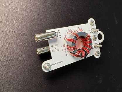
2) Before applying the heat shrink you can use the zip tie to secure the toroids using the 2 hole in the board. Apply the heat shrink leaving the top and bottom bolts expose and you're good to go. You may or may not need to trim the heat shrink a little.


NOTES:
There is a lot of information online on use cases for these transformers along with wire lengths and deployment configurations. I don't get into the nitty gritty of that here. You could use them in many different ways. It's ham radio have fun and experiment.